TL/DR
This guide covers the foundational engineering principles behind microcontrollers and radio frequency systems, progressing from core embedded hardware concepts through communication protocols, RF physics, and practical antenna design. It examines specific chips including the ESP32, CC1101, NRF24L01+, and PN532, explaining their roles in wireless systems.
Real-world case studies on wireless keyboards and car key fobs illustrate how frequency selection, modulation schemes, and security mechanisms like rolling codes are applied in practice. The material is structured as a technical curriculum with definitions, analogies, and comprehension questions throughout.
Introduction
The integration of computational logic with electromagnetic transmission forms the backbone of the modern Internet of Things (IoT) and wireless infrastructure. This report provides an exhaustive examination of the engineering principles governing microcontrollers and radio frequency (RF) systems, structured as a progressive technical curriculum.
Part 1: The Foundation — How Embedded Systems Work
Lesson 1: Microcontrollers 101 — The Computational Brain
A microcontroller (often abbreviated MCU) is essentially a small computer on a single chip designed to control a specific device or task, rather than run many unrelated applications like a laptop. It acts as a special-purpose controller inside other products.
Key Definitions
- Integrated Circuit (IC): An electronic circuit manufactured onto a small piece of semiconductor material (a “chip”).
- Semiconductor: A material (like silicon) whose ability to conduct electricity can be controlled — this controllability is what makes transistors and computers possible.
- Embedded System: The whole product that contains the microcontroller (and sensors, motors, displays, etc.) and does a dedicated job — think “microwave oven controller” or “thermostat controller”. The MCU is the brain, but the embedded system includes the rest of the hardware.
MCU vs. CPU vs. SoC
A CPU (central burying unit) is the part that executes instructions. In a desktop, the CPU is one piece of a system with separate memory and storage chips. A microprocessor is typically “just the CPU” and expects external hardware. By contrast, an MCU integrates the CPU, memory, and I/O features on one chip.
A System-on-Chip (SoC) is a chip that integrates many system functions together — often including one or more CPU cores, memory interfaces, and sophisticated peripherals like radios or graphics blocks. Many modern MCUs, like the ESP32, are also SoCs. Integrating these functions means smaller circuit boards, lower cost, and better reliability.
Core Building Blocks: The Kitchen Analogy
Nearly every microcontroller can be understood through four “chunks”:
| Component | Function | Kitchen Analogy |
|---|---|---|
| CPU | Executes a sequence of instructions (Firmware). | The Chef |
| RAM | Volatile working memory for temporary data while the program runs. | The Countertop (active workspace) |
| Flash / ROM | Non-volatile storage that keeps contents without power; stores firmware. | The Recipe Book (stored instructions) |
| Peripherals | Specialized hardware for tasks like timers, ADCs, or serial interfaces. | The Appliances (oven, blender) |
Other Vital Components:
- GPIO (General Purpose Input/Output): The “digital legs” of the chip. Each pin can be an input (reading a button) or an output (driving an LED).
- Clock: The timing heartbeat that steps a digital system forward, often from an oscillator (e.g., a 40 MHz crystal).
- Interrupt: A hardware signal telling the CPU to “stop and handle this now,” managed by an interrupt controller.
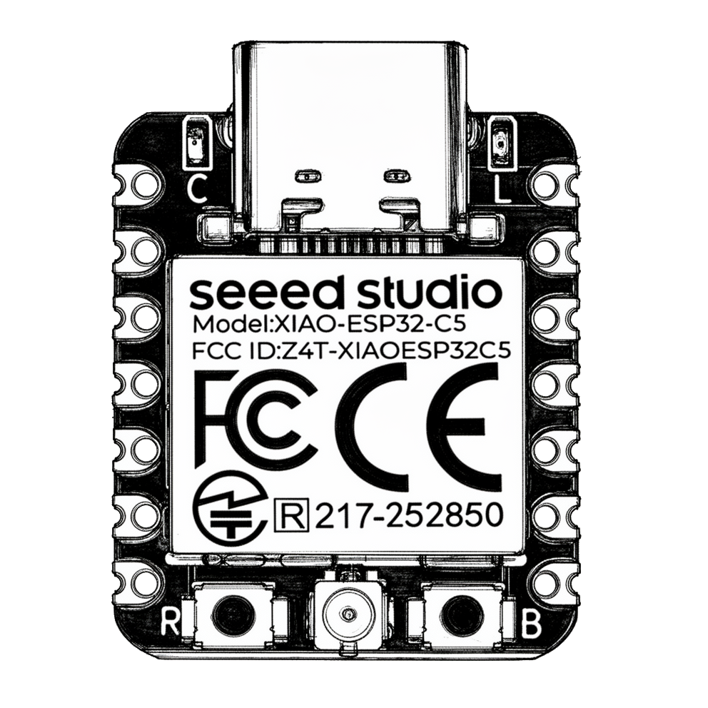
The ESP32: A Modern SoC
The original ESP32 from Espressif is a 2.4 GHz Wi‑Fi and Bluetooth combo chip.
- CPU: It uses Xtensa dual-core 32-bit LX6 cores.
- Memory: It includes 448 KB ROM and 520 KB SRAM on-chip.
- Architecture: It uses a Harvard Architecture, meaning it has separate pathways (buses) for instructions and data to improve speed.
Sanity Rule: “ESP32” is a family. The ESP32-S3 uses LX7 cores, while the ESP32-C3 uses a RISC-V core.
Real-World Example: Cheap Yellow Display (CYD)
A development board like the CYD (official model ESP32-2432S028R) makes prototyping easier by exposing pins and power.
- The Module: Most use an ESP32-WROOM-32 module, which packages the SoC with 4 MB of external SPI flash and a crystal oscillator.
- The Display: A TFT LCD driven by an ILI9341 controller chip.
- Expansion: Breakout pins allow you to connect external modules like a CC1101 or NRF24L01. Note that some GPIOs (6 to 11) are unavailable because they connect to the internal flash.
Understanding Check
- What is the difference between a microcontroller and a microprocessor?
- In the kitchen analogy: what do RAM and flash correspond to, and why are they different kinds of “memory”?
- What does GPIO mean, and why would an embedded board “break out” GPIO pins to headers?
- The ESP32 technical manual calls the CPU design Harvard architecture. What is separated in a Harvard architecture, and why might that be useful?
- If a CYD board includes an ESP32-WROOM-32 module with integrated flash, why might some GPIOs be unavailable for your own wiring — even though the chip “has lots of pins”?
Lesson 2: How Chips Talk — Communication Protocols
In the world of embedded systems, a “protocol” is an agreed-upon set of rules — a digital handshake — that allows different chips to exchange information accurately.
The Great Divide: Synchronous vs. Asynchronous
- Synchronous: Chips share a Clock (CLK) wire. One chip (the Controller) pulses this wire like a metronome, and both chips send or read data exactly on those pulses.
- Asynchronous: There is no shared clock wire. Both chips must be pre-set to the exact same speed, known as a Baud Rate.
UART (Universal Asynchronous Receiver-Transmitter)
UART is the oldest and simplest protocol, using only TX (Transmit) and RX (Receive) wires.
- How it works: Because it is asynchronous, UART adds “Start” and “Stop” bits to every byte to align the receiver.
- Configuration: The most common setting is 8N1 (8 data bits, No parity, 1 stop bit).
- The Physics: It relies on precise internal timers and can typically only tolerate a timing error of about ±2-3% before data is corrupted.
- Real-World Example: GPS Modules stream text data (NMEA sentences) over UART.
- Tool Connection: USB-to-Serial chips (like the CH340 on the CYD) convert USB data into UART for the MCU.
SPI (Serial Peripheral Interface)
SPI is a high-speed synchronous protocol typically requiring four wires: SCK (Clock), MOSI (Controller Out), MISO (Controller In), and CS (Chip Select).
- The Librarian Analogy: A librarian (Controller) points at a specific student (Peripheral) by pulling the Chip Select wire “Low”. Only that student listens and responds.
- Speed: SPI can reach massive speeds (up to 80 Mbps), far exceeding standard UART.
- Real-World Example: High-performance radio chips like the CC1101 and NRF24L01 use SPI to move data quickly.
I2C (Inter-Integrated Circuit)
I2C is an efficient “bus” protocol using only two wires: SDA (Data) and SCL (Clock).
- The Mailbox Analogy: All chips share the same wires. Each chip has a unique numerical Address. The Controller sends an address, and only the matching chip responds.
- Features: I2C is slower than SPI but supports up to 127 devices on just two pins. It requires “Pull-up Resistors” to keep the lines at a stable high voltage when idle.
- Real-World Example: Environmental Sensors (temperature, humidity) commonly use I2C.
Mini-Glossary
- Full-Duplex: Simultaneous two-way communication (SPI, UART).
- Half-Duplex: One-way communication at a time (I2C).
- Baud Rate: The bit-per-second speed of asynchronous communication.
Understanding Check
- If you set your GPS module to 9600 baud but your ESP32 is listening at 115200 baud, what will the output look like in your code?
- In a Synchronous protocol like SPI, why don’t the two chips need to agree on a “Baud Rate” beforehand?
- Based on the “Librarian Analogy,” what happens if the Controller wants to talk to a second SPI device while the first one is already talking?
- Why is I2C often preferred for a board that has 10 different tiny sensors on it, even if it’s slower than SPI?
- Why do high-performance radio chips like the CC1101 use SPI instead of the simpler UART protocol?
Part 2: Understanding Radio Waves
Lesson 3: RF Basics — What Are Radio Waves?
Radio frequency (RF) signals are electromagnetic waves that oscillate at specific frequencies. These waves consist of oscillating electric and magnetic fields that travel through space at the speed of light ($c \approx 300,000$ km/s).
Key Concepts and Properties
- Frequency ($f$): Measured in Hertz (Hz), this is the number of wave cycles that pass a point in one second.
- Wavelength ($\lambda$): The physical distance between two consecutive wave peaks. Wavelength and frequency are inversely proportional, governed by $c = f \cdot \lambda$. Higher frequencies have shorter physical waves.
- Amplitude: The “height” or power of the wave. At a receiver, this is often expressed as RSSI (Received Signal Strength Indicator), measured in dBm (decibel-milliwatts). A sensitivity of -116 dBm means a chip can “hear” extremely quiet signals.
The Physics of Propagation
The size of a wave determines how it interacts with the world. Lower frequencies (longer waves) have better penetration, meaning they can pass through walls and obstacles more easily than higher frequencies (shorter waves).
Lesson 4: The RF Spectrum Tour
Wireless communication is organized into “bands” — specific ranges of frequencies reserved for certain types of devices.
Sub-GHz (300 MHz to 928 MHz)
- Properties: Exceptional range and wall penetration. Low path loss means signals travel further with less power.
- Data Rate: Typically low (0.6 kbps to 500 kbps).
- Devices: Garage door openers, car key fobs (315/433 MHz), weather sensors, and long-range industrial monitors.
- Tool Connection: When you see “Sub-GHz” in a tool like HaleHound, it is using a chip like the CC1101 to talk to these devices.
2.4 GHz Band (2.400 GHz to 2.4835 GHz)
- Properties: A globally unlicensed band. It is extremely congested because many devices (WiFi, Bluetooth, microwaves) compete for the same space.
- Data Rate: High (up to 2 Mbps for chips like NRF24L01, or 150 Mbps for WiFi).
- Devices: WiFi routers, Bluetooth speakers, wireless mice, baby monitors.
- Tool Connection: This is the native playground of the ESP32 and chips like the NRF24L01.
5 GHz and Beyond
Properties: Higher data rates but very poor wall penetration. It is used primarily for modern high-speed WiFi (WiFi 5/6).
| Band | Typical Frequency | Penetration | Range | Primary Use |
|---|---|---|---|---|
| Sub-GHz | 433 MHz / 868 MHz | Excellent | High | Remotes, Long-range sensors |
| 2.4 GHz | 2400 MHz (2.4 GHz) | Moderate | Moderate | WiFi, Bluetooth, Mice |
| 5 GHz | 5000 MHz (5 GHz) | Poor | Low | High-speed WiFi |
Lesson 5: How Information Rides on Radio Waves (Modulation)
To send data (1s and 0s), we must change the carrier wave in a specific way. This is called Modulation.
- ASK / OOK (Amplitude Shift Keying / On-Off Keying): The wave is turned on for a ‘1’ and off for a ‘0’. It is the simplest but most susceptible to noise. Example: Basic 433 MHz doorbells.
- FSK (Frequency Shift Keying): The transmitter shifts between two slightly different frequencies to represent bits. It is much more resistant to interference than ASK. Example: Modern car fobs.
- GFSK (Gaussian Frequency Shift Keying): A “smoothed” version of FSK that prevents the signal from leaking into other channels. Example: Bluetooth Low Energy (BLE) and wireless keyboards.
Why Modulation Matters
Different modulations are like different languages. Even if two devices are on the same frequency (e.g., 433.92 MHz), an OOK receiver cannot understand an FSK signal. This is why radio chips like the CC1101 are valued; they are “multi-lingual” and can be programmed to use ASK, FSK, or GFSK.
Part 3: The Hardware — Radio Modules
Microcontrollers rely on specialized radio chips to handle the high-speed physics of RF transmission. These chips act as “RF front-ends” for the system.
Lesson 6: The CC1101 — Sub-GHz Transceiver
The CC1101 is a versatile, single-chip sub-GHz transceiver from Texas Instruments. It is an industry standard for low-power wireless applications requiring long-range or obstacle penetration.
- Key Capabilities: It is highly programmable, allowing a microcontroller to set its frequency anywhere from 300 MHz to 928 MHz. It supports multiple modulations, including 2-FSK, GFSK, ASK/OOK, and MSK.
- Wiring: It communicates via SPI (MOSI, MISO, SCK, CSN). It also features GDO0 and GDO2 pins, which provide digital outputs for status or interrupts (e.g., “I just received a packet”).
- Voltage: It operates between 1.8V and 3.6V. Caution: It is not 5V tolerant, so connecting it directly to a 5V Arduino without level shifters can damage the chip.
- Sensitivity: It is famous for its high sensitivity of -116 dBm at 0.6 kbps, allowing it to hear faint signals from hundreds of meters away.
Lesson 7: The NRF24L01+ — 2.4 GHz Multi-Protocol Chip
The NRF24L01+ is a popular 2.4 GHz transceiver optimized for high-speed, low-power data transfer in short to medium ranges.
- Key Capabilities: It provides air data rates of 250 kbps, 1 Mbps, and 2 Mbps. Unlike the CC1101, it features Enhanced ShockBurst™, which automatically handles packet acknowledgement and retransmission in hardware, simplifying code for the user.
- The “+PA+LNA” Variant: Many modules include a Power Amplifier (PA) to boost transmission and a Low-Noise Amplifier (LNA) to increase receive sensitivity, significantly extending its range.
- Wiring: It uses SPI plus an extra CE (Chip Enable) pin to switch the module between “listening” (receive) and “active” (transmit) modes.
- Real-World Application: Used in wireless mice, keyboards, and drones because its high data rate allows for “near immediate” packet delivery.
Lesson 8: The PN532 — NFC/RFID Reader
The PN532 is a highly integrated module for Near Field Communication (NFC) at 13.56 MHz.
- Key Capabilities: It uses inductive coupling to transfer data and power over short distances (centimeters). It can read/write various tags (MIFARE Classic, FeliCa) and even perform peer-to-peer data transfer.
- Hardware Security: It features hardware AES acceleration, which it uses to decrypt and clone tags like MIFARE Classic, commonly used in office access badges.
- Interface: It is unique because it supports multiple protocols, including I2C, SPI, and UART, selectable via physical switches on the module.
Lesson 9: The ESP32’s Built-in Radios
The ESP32 is a System-in-Package (SiP) or SoC that includes a dedicated 2.4 GHz radio block on the silicon.
- WiFi: Supports 802.11 b/g/n, providing internet connectivity and web-server capabilities.
- Bluetooth: Supports both Bluetooth Classic (v4.2) for high-speed data and Bluetooth Low Energy (BLE) for battery-efficient sensing.
- Architecture Advantage: Because it is dual-core, the ESP32 can dedicate one CPU core (PRO_CPU) to managing the heavy timing requirements of the WiFi/Bluetooth radio stack, while the other (APP_CPU) runs your application code. This prevents your program from lagging while the radio is transmitting data.
| Module | Frequency | Interface | Key Strength |
|---|---|---|---|
| CC1101 | 300–928 MHz | SPI | Penetrates walls; massive range |
| NRF24L01+ | 2.4 GHz | SPI + CE | High speed; auto-retransmit |
| PN532 | 13.56 MHz | SPI/I2C/UART | NFC/RFID tag cloning |
| ESP32 Internal | 2.4 GHz | Internal | Integrated WiFi/Bluetooth |
Understanding Check
- Pin Identification: You are wiring an NRF24L01+ and notice a pin labeled CE. What is its purpose, and how does it differ from the CS (Chip Select) pin?
- Voltage Safety: Why must you be careful when connecting a CC1101 module directly to a standard 5V microcontroller like an Arduino Uno?
- Feature Logic: How does the PN532 “power” a library book tag that has no battery of its own?
- Hardware Selection: If you wanted to build a drone controller that requires “near immediate” response and a high data rate, would you use the CC1101 or the NRF24L01+?
- ESP32 Logic: Why is the ESP32’s dual-core design useful when you are running a complex display (like on the CYD) while also transmitting data over WiFi?
Part 4: Antennas and Practical Considerations
Lesson 10: Antenna Basics for Makers
An antenna is a specialized transducer that bridges the world of electrical circuits and the invisible realm of radio waves. It performs two essential jobs: converting an alternating electrical current into radiating electromagnetic waves (transmission) or intercepting passing waves to generate a faint alternating current (reception).
The Physics of Radiation
When a transmitter applies an oscillating current to an antenna, it forces electrons within the metal conductor to vibrate back and forth millions of times per second. This frantic movement of electrical charge generates an electric field loop that radiates away from the antenna as a radio wave. These waves travel at the speed of light ($c \approx 300,000$ km/s).
Wavelength and Resonance
For an antenna to be efficient, its physical length must be mathematically related to the wavelength ($\lambda$) of the signal it is handling. This principle is called resonance. An antenna of the correct length “resonates” with the radio wave, much like pushing a child on a swing at just the right moment sends them higher.
The most common design for hobbyists is the quarter-wave monopole antenna ($\lambda/4$). The formula to calculate its length is:
$$Length (m) = \frac{300}{f (MHz)} \times 0.25 \times 0.96$$
(Where 300 is a constant representing the speed of light in millions of meters/sec, 0.25 represents the quarter-wave fraction, and 0.96 is a shortening factor for the speed of the signal in wire vs. air.)
- Example (433 MHz): $\frac{300}{433} \times 0.25 \times 0.96 \approx 0.166$ m (or 16.6 cm).
- Example (2.4 GHz): $\frac{300}{2400} \times 0.25 \times 0.96 \approx 0.03$ m (or 3 cm).
Gain and Radiation Patterns
- Omnidirectional: Radiates energy equally in a 360-degree horizontal pattern (shaped like a donut). This is common for whip or rubber-ducky antennas found on devices like the CYD.
- Directional: Focuses energy in a specific direction (like a flashlight beam), such as a Yagi or satellite dish.
- Gain (dBi): A measure of how much an antenna focuses its energy compared to an ideal theoretical point (isotropic radiator).
Impedance Matching (The 50 Ohm Standard)
To ensure maximum power transfer from the radio chip to the antenna, their “electrical resistance” or impedance must match (typically 50 Ohms). An analogy is connecting two water pipes: if one is huge and the other is narrow, the mismatch causes “turbulence” (reflections), where power bounces back into the chip as heat instead of radiating as a wave.
Lesson 11: Power, Range, and Real-World Limitations
Several factors dictate the actual “reach” of your embedded system in the real world:
- Transmit Power (dBm): The starting strength of the signal. Higher power increases range but drains batteries faster.
- Receiver Sensitivity: The quietest signal a chip can reliably hear. High-quality chips like the CC1101 have sensitivities as low as -116 dBm.
- Path Loss: Signals naturally weaken as they spread out through space (geometric spreading).
- Penetration vs. Frequency: Lower frequencies (Sub-GHz) have longer wavelengths that “bend” around obstacles or pass through walls better than high frequencies (2.4 GHz / 5 GHz).
- Interference (Congestion): The 2.4 GHz band is famously “noisy” because it is crowded with WiFi, Bluetooth, and microwave ovens, all competing for the same spectrum.
Understanding Check
- Math: Using the formula $Length (m) = (300 / f) \times 0.25 \times 0.96$, calculate the approximate length of a quarter-wave antenna for a 315 MHz car key fob.
- Analogy: If you connect a 50 Ohm radio chip to a 300 Ohm antenna without a matching circuit, what happens to the power that was supposed to be transmitted?
- Concept: Why does an omnidirectional antenna have a “donut-shaped” pattern rather than a perfect sphere?
- Application: You are designing a system to monitor soil moisture across a 2-kilometer farm. Why would you choose a 433 MHz module with a long whip antenna over a 2.4 GHz module with a tiny PCB antenna?
- Sensitivity: Which chip is more powerful: one that can hear a signal at -90 dBm or one that can hear a signal at -110 dBm?
Part 5: Bringing It All Together
Lesson 12: Case Study — A Wireless Keyboard
A wireless keyboard illustrates how high-speed data meets low-power design.
- Frequency and Hardware: Most modern keyboards operate in the 2.4 GHz ISM band. They often use proprietary chips like the NRF24L01+ or standardized Bluetooth Low Energy (BLE) modules.
- Protocol and Logic: When a key is pressed, the internal microcontroller (the “brain”) detects the event and prepares a data packet. If using an NRF24-style chip, it might utilize the Enhanced ShockBurst™ protocol, which automatically handles the handshaking and retransmissions needed to ensure the computer actually received the keystroke.
- Modulation: These devices almost exclusively use GFSK (Gaussian Frequency Shift Keying). This smoothing of the signal prevents the high-speed data from interfering with other nearby 2.4 GHz devices, like your WiFi router.
- Observation: A tool like HaleHound can identify these devices by their 2.4 GHz “signature,” even if the actual keystrokes are encrypted.
Lesson 13: Case Study — A Car Key Fob
A car key fob is an exercise in reliability and security over long distances.
- Frequency and Hardware: Key fobs typically use Sub-GHz bands (315 MHz or 433 MHz) because these waves easily pass through the metal and glass of a car or the brick walls of a house. The receiver in the car often utilizes a versatile chip like the CC1101 to handle these transmissions.
- Modulation: While old fobs used simple ASK/OOK, modern systems often use FSK (Frequency Shift Keying) to improve immunity to electrical noise found in parking lots.
- Security (Rolling Codes): This is the most critical feature. Every time you press the button, the fob and the car calculate a new unique code based on a shared secret and a counter. If the code matches what the car expects, it opens. This prevents a simple “replay” where someone records the signal and plays it back later.
- Observation: Tools can observe these signals, and analyzing the “rolling code” logic is a primary focus for researchers studying automotive security.
Final Synthesis Questions
- Hardware Choice: You are building a remote-controlled boat. You need it to work from a long distance and pass through some reeds and docks. Based on Lesson 4 and Lesson 11, which frequency band and which radio chip from Part 3 would you select?
- Communication Flow: Explain the path a “Button Press” takes, starting from the GPIO pin (Lesson 1), through a protocol (Lesson 2), into a radio module (Part 3), and finally out an antenna (Part 4).
- Security Logic: Why would a wireless keyboard (which works at 2.4 GHz) be less likely to use “Rolling Codes” than a car key fob (which works at 433 MHz)?
- Protocol Identification: If you see a radio module with 4 pins labeled MOSI, MISO, SCK, and CS, which “language” from Lesson 2 is it speaking?
- Antenna Troubleshooting: You have a 433 MHz system that is getting very poor range. You check the antenna and find it is exactly 3 cm long. Based on the math in Lesson 10, why is this a problem?
This concludes the comprehensive foundational curriculum. By understanding the link between microcontrollers, digital protocols, and the physics of radio waves, you now have a solid framework for analyzing and building any modern wireless embedded system.